Product Description:
1、 Product Overview:
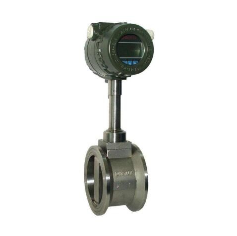
The LUGB series vortex flowmeter is mainly used for flow measurement of industrial pipeline media fluids, such as gases, liquids, vapors, and other media. Its characteristics are small pressure loss, large range, high accuracy, and almost unaffected by parameters such as fluid density, pressure, temperature, viscosity, etc. when measuring volumetric flow rate under working conditions. No movable mechanical parts, therefore high reliability and low maintenance. The instrument parameters can remain stable for a long time. This instrument uses piezoelectric stress sensors with high reliability and can operate within a temperature range of -20 ℃ to+250 ℃. It has both analog standard signals and digital pulse signal outputs, making it easy to use in conjunction with digital systems such as computers. It is an ideal flowmeter.
As can be seen from the above equation, the pulse frequency signal output by VSF is not affected by fluid properties and composition changes, that is, the instrument coefficient is only related to the shape and size of the vortex generator and pipeline within a certain Reynolds number range. However, as a flowmeter in material balance and energy measurement, it is necessary to detect mass flow rate. At this time, the output signal of the flowmeter should simultaneously monitor volume flow rate and fluid density. Fluid properties and components still have a direct impact on flow measurement.
The LUGB series vortex flowmeter is a new type of flowmeter for measuring fluid flow in closed pipelines based on the Karman vortex principle. Due to its excellent medium adaptability, it can directly measure the volumetric flow rate of steam, air, gas, water, and liquid without temperature and pressure compensation. Equipped with temperature and pressure sensors, it can measure standard volumetric flow rate and mass flow rate, making it an ideal alternative to throttling flow meters.
To improve the high temperature resistance and vibration resistance of the vortex flowmeter, our company's LUG improved vortex flowmeter sensor can be used in harsh working conditions such as high temperature (350 ℃) and strong vibration (≤ 1g) due to its structure and material selection.
In practical applications, large flow rates are often much lower than the upper limit value of the instrument, and with changes in load, small flow rates often fall below the lower limit value of the instrument. The instrument does not work in the working section. To solve this problem, it is usually used to reduce the diameter at the measuring point to increase the flow rate at the measuring point, and instruments are selected to facilitate the measurement of the instrument. However, this variable diameter method requires a straight pipe section with a length of more than 15D between the variable diameter pipe and the instrument for rectification, which makes processing and installation inconvenient. Our company has developed an LGZ variable diameter rectifier with a curved longitudinal section, which has multiple functions such as rectification, increasing flow velocity, and changing flow velocity distribution. Its structural size is small, only one-third of the inner diameter of the process pipe, and it is integrated with the vortex flowmeter. It not only does not require an additional straight pipe section, but also reduces the requirements for the straight pipe section of the process pipe, making installation very convenient.
For the convenience of use, the battery powered local display vortex flowmeter adopts low-power high-tech. It can operate continuously for more than a year with lithium battery power supply, saving the procurement and installation costs of cables and display instruments. It can display instantaneous flow, cumulative flow, etc. on site. The temperature compensated integrated vortex flowmeter also comes with a temperature sensor, which can directly measure the temperature of saturated steam and calculate the pressure, thereby displaying the mass flow rate of saturated steam. The temperature pressure compensation integrated type is equipped with temperature and pressure sensors, which can directly measure the temperature and pressure of the gas medium for gas flow measurement, thereby displaying the standard volume flow rate of the gas.
2、 Working principle:
The LUGB series vortex flowmeter consists of a vortex generator designed in the flow field, a detection probe, and corresponding electronic circuits. When the fluid flows through a vortex generator, two alternating rows of vortices are formed on both sides, which are called Karman vortex streets. On the basis of the Karman vortex street theory, it was proposed that the frequency of the Karman vortex street is proportional to the flow velocity of the fluid, and the relationship between frequency and flow velocity was given
In the formula f=St × V/d:
Frequency of vortex street occurrence (Hz)
Average velocity on both sides of the vortex generator (m/s)
St Strohal coefficient (constant)
These alternating vortices form a series of alternating negative pressures, which act on the detection probe to generate a series of alternating electrical signals. After conversion, shaping, and amplification by a preamplifier, the output is a pulse frequency signal (or standard signal) proportional to the synchronization with the vortices.
3、 Usage selection and application:
1. For the convenience of use, the battery powered type adopts low-power high-tech, and can operate continuously for more than a year using lithium battery power supply, saving the procurement and installation costs of cables and display instruments. It can display instantaneous flow, cumulative flow, etc. on site.
2. The temperature compensation integrated model also comes with a temperature sensor, which can directly measure the temperature of saturated steam and calculate the pressure, thereby displaying the mass flow rate of saturated steam.
3. The temperature pressure compensation integrated type is equipped with temperature and pressure sensors, which can directly measure the temperature and pressure of the gas medium for gas flow measurement, thereby displaying the standard volume flow rate of the gas.
4. Widely used in the process measurement and energy-saving management of various low viscosity single-phase fluids such as liquids, gases, steam, etc. in industries such as petroleum, chemical, metallurgy, machinery, papermaking, as well as urban pipeline heating, water supply, gas, etc.
4、 Main features:
1. Can accurately measure the flow rates of gases, liquids, and vapors over a wide range of flow rates without being affected by fluid physical properties;
2. Not affected by temperature and pressure, and not easily clogged, stuck, or scaled, resistant to high temperatures and pressures;
3. Safe and explosion-proof, suitable for harsh environments;
4. No movable parts, no holes or gaps design, the product is wear-resistant, dirt resistant, does not require mechanical maintenance, and has a long service life;
5. Adopting low-power high-tech and battery powered on-site display flowmeter, it can operate continuously without electricity for more than two years;
6. Integrated design of temperature and pressure compensation;
7. The current output is all electrically isolated, with good common mode interference suppression capability;
8. Simultaneously display the flow value and cumulative flow value, without the need to switch between them;
9. Adopting anti vibration probes to effectively eliminate the influence of external vibrations;
10. Adopting a split type signal converter with a cable length of 100 meters;
11. The range ratio is up to 20:1;
12. The overall structure design of the instrument is reasonable, with a wide dynamic measurement range and low pressure loss;
13. The body is made of stainless steel material, which is suitable for measuring corrosive media;
14. On site LCD display, pulse, 4-20mA output or 485 communication, can be connected to industrial automation systems.
5、 Technical parameters:
1. Measurement medium: gas, liquid, vapor;
2. Connection methods: flange card type, flange type, plug-in type;
3. The caliber specification for flange card mounted calibers is 25, 32, 50, 80, and 100;
4. The selection of flange connection caliber is 100, 150, 200;
5. Flow range (see flow range table)
6. The normal measurement flow rate range is Reynolds number 1.5 × 10⁴ to 4 × 10⁶; Gas velocity of 5-50m/s; Liquid 0.5-7m/s;
7. Measurement accuracy of 1.0 level and 1.5 level;
8. Temperature of the tested medium: normal temperature -25 ℃~100 ℃, high temperature -25 ℃~150 ℃ -25 ℃~250 ℃;
9. Output signal pulse voltage output signal high level 8-10V low level 0.7-1.3V;
10. Pulse duty cycle of about 50%, transmission distance of 100m;
11. Pulse current remote transmission signal 4-20 mA, transmission distance of 1000m;
12. Instrument operating environment temperature: -25 ℃~+55 ℃ humidity: 5-90% RH50 ℃;
13. Material: stainless steel, aluminum alloy;
14. Power supply DC24V or lithium battery 3.6V;
15. Explosion proof level: intrinsic safety type iaIIbT3-T6, protection level: IP65.
6、 Installation requirements:
1. Vortex street can only measure in one direction. When installing, pay attention to ensuring that the direction of medium flow is consistent with the direction indicated by the flow meter arrow.
2. The installation method is vertical installation, and the medium passes through the flowmeter from bottom to top. Install the flowmeter on a vertical pipeline with a flow direction from bottom to top.
3. When installing horizontally, the flowmeter must be installed in the high-pressure area of the entire system and ensure the corresponding outlet pressure; Do not install it at the highest point of the pipeline, as gas often accumulates at this point. If the pipeline is not full, the outlet cannot be directly vented.
4. When measuring high-temperature fluids, try to use a vertical installation method as much as possible; If horizontal installation is necessary, please install the transmitter part of the flowmeter vertically downwards or horizontally on the side to avoid excessive temperature; Pay attention to good air flow or ventilation at the installation location.
5. Requirement for straight pipe section: Ensure at least 15 times the diameter of the pipe in front of the flowmeter and 5 times the diameter behind the flowmeter. If there are interference sources such as bends, indentations, and expansions in front of the flowmeter, it is necessary to ensure a diameter of 30-40 times the diameter in front of the flowmeter and 6 times the diameter behind the flowmeter. The flowmeter should be installed upstream of the regulating valve, pressure or temperature sensor.
6. During installation, it should be noted that the diameter of the pipeline should be slightly larger than or equal to the inner diameter of the instrument.
7. When using a sealing ring, it should be noted that the inner diameter of the sealing ring should be slightly larger than or equal to the inner diameter of the instrument, and the center of the sealing ring should be located at the center of the pipeline.
8. When sealing the electrical connection of cable entry instruments, attention must be paid to the sealing of the inlet holes. Select the corresponding sealing interface (M20 X 1.5; 1/2'NPT; G1/2 ') according to the instrument cable entry model, and install it correctly and tightly. Without sealed joints or careless installation, the sealing effect cannot be achieved.


 English