Product Description:
1、 Product Overview:
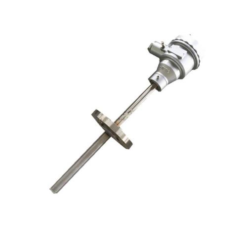
The LGK series orifice flowmeter is a high range ratio differential pressure flow device composed of a standard orifice plate and a multi parameter differential pressure transmitter (or differential pressure transmitter, temperature transmitter, and pressure transmitter). It can measure the flow of gas, steam, liquid, and induced flow, and is widely used in process control and measurement in fields such as petroleum, chemical, metallurgy, power, heating, and water supply. The throttling device, also known as the differential pressure flowmeter, consists of a primary detection element (throttling element) and a secondary device (differential pressure transmitter and flow display instrument), which are widely used in gas applications. Flow measurement of steam and liquid. It has a simple structure, easy maintenance, and stable performance.
2、 Working principle:
The LGK series orifice flowmeter is a type of flow meter that, when the fluid filled in the pipeline flows through the flow orifice plate inside the pipeline, the flow velocity will locally contract at the throttling point of the flow orifice plate, thereby accelerating the flow velocity and reducing the static pressure. As a result, a pressure drop or pressure difference is generated before and after the standard orifice plate. The larger the flow rate of the medium, the greater the pressure difference generated before and after the flow orifice plate. Therefore, the size of fluid flow can be measured by measuring the pressure difference. This measurement method is based on the principles of flow continuity equation (law of conservation of mass) and Bernoulli equation (law of conservation of energy). Under the condition of known parameters, the relationship between differential pressure and flow rate can be derived based on the principle of flow continuity and Bernoulli equation to obtain the flow rate. The basic formula is as follows:

C - Non dimensional outflow coefficient
D - Diameter of the orifice or throat of the throttling element under working conditions
D - Inner diameter of upstream pipeline under working conditions
QM - Mass flow rate Kg/s
Qv - Volume flow rate m3/s
The diameter ratio d/D is dimensionless
Density of fluid Kg/m3
The coefficient of expandability is dimensionless

3、 Application scenarios:
The LGK series orifice flowmeter is a high range ratio differential pressure flow device composed of a standard orifice plate and a multi parameter differential pressure transmitter (or differential pressure transmitter, temperature transmitter, and pressure transmitter). It can measure the flow of gas, steam, liquid, and natural gas, and is widely used in process control and measurement in the fields of petroleum, chemical, metallurgy, power, heating, water supply, etc.
4、 Main features:
1. The structure of the throttling device is easy to replicate, simple and sturdy, with stable and reliable performance, long service life, and low price.
2. The calculation of orifice plates adopts international standards and processing.
3. Widely applicable, all single-phase flows can be measured, and some mixed phase flows can also be applied.
4. The standard throttling device does not require real flow calibration and can be put into use.
5. The installation of integrated orifice plates is simpler, without the need for pressure pipes, and can be directly connected to differential pressure transmitters and pressure transmitters.
5、 Technical parameters:
Caliber: DN25~DN1000(mm);
Accuracy: ± 1% FS;
Range ratio: standard 1:13, extended 1:30;
Work pressure: ≤ 42.0MPa;
Medium temperature:- 40C~450C;
Medium viscosity: ≤ 30CP (equivalent to heavy oil);
β value: 0.2-0.8;
Connection method: flange or clamp type;
Flange standard:
DN≤600mm, PN2.0~PN26,HG20616; PN32,HG20618;
DN>600mm,PN2.0~PN15,HG20623;
It can also be manufactured according to the flange standards provided by the user;
Material: Main body, orifice plate, pressure tapping tube, three valve group: stainless steel; Straight pipe section and connecting flange: carbon steel or stainless steel;
Installation method: horizontal or vertical;
Intelligent differential pressure transmitter: output: 4-20mA DC or digital signal; Power supply: 24V DC;
Explosion proof grade: d Ⅱ CT5.6, ia Ⅱ CT4-6; Protection level: IP67;
Header: There are two types: blind meter and digital meter.
6、 Classification explanation of structural characteristics:
1. Ring chamber pressure standard orifice plate:
It belongs to the standard orifice plate. Due to the implementation of ring chamber pressure measurement, measurement accuracy has been improved and the length of the smallest straight pipe segment required for installation has been shortened, making it widely applicable in various departments.
2. Corner joint single d.u drilling pressure standard orifice plate:
It belongs to the standard orifice plate. When the pipe diameter is above 400 millimeters, this form is often used. The pressure measurement methods include flange drilling, circular pressure equalization ring, or square pressure equalization ring. The orifice plate can be in the form of a handle hole or a non-standard circular hole plate.
3. Flange pressure gauge standard orifice plate:
It belongs to the standard orifice plate. Regardless of the diameter of the pipeline, the centers of the upstream and downstream pressure tapping holes are located at 1 hour (25.5mm) each from the end faces on both sides of the orifice plate. This form is commonly used in refining systems.
4. Radial distance pressure standard orifice plate:
It belongs to the standard orifice plate. The pressure measurement method is pipeline pressure measurement. The center of the upstream pressure tapping hole is located at twice the inner diameter of the pipeline in front of the orifice plate. The center of the downstream pressure tapping hole is located at a distance of half the inner diameter of the pipe from the rear end face of the orifice plate.
5. Orifice plate:
Belongs to non-standard orifice plate. Used for measuring fluids within a diameter of 10mm to 50mm.
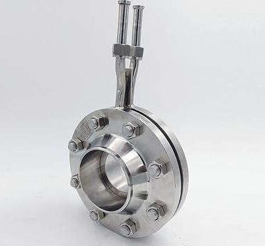
6. Double orifice plate:
It is composed of two standard orifice plates installed at a certain distance from each other in a straight pipe. In terms of the direction of the flow, the front orifice is referred to as the auxiliary orifice plate, while the rear orifice plate is referred to as the main orifice plate. The cross-sectional ratio m1 of the auxiliary orifice plate is greater than the cross-sectional ratio m of the main orifice plate. Two orifice plates form a nozzle with a liquid wall. It is used for flow measurement of low Reynolds number fluids or high viscosity fluids.
7. Circular perforated plate:
It belongs to non-standard orifice plates and is suitable for measuring the flow rate of fluids that are dirty, have air bubbles, or contain solid particles. Its measurement accuracy is relatively low.
8. Conical inlet orifice plate:
Belongs to non-standard orifice plate. The angle between the circular cone and the centerline is 45 °. This conical inlet orifice plate is suitable for applications with low Reynolds numbers, but the pipe size must not be less than 25 millimeters.


 English